Here, is a very interesting and simple
project in the series of communication used
to transmit noise free F.M. signal in the
wide range up to 100 M using only one
transistor. The transmitted message from
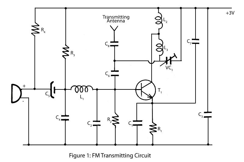
F.M. transmitter circuit is received by the receiver having the facilities of F.M. Circuit Description of simple F.M. transmitter The entire circuit of F.M. transmitter is
divided into three major stage i.e. oscillator,
modulator and amplifier. The transmitting
frequency of 88-108 MHz is generated by
adjusting VC1. The input voice given to microphone is changed into electric signal
and is given to base of transistor T1. Transistor T1 is used as oscillator which oscillates the frequency of 88-108 MHz.
The oscillated frequency is depended upon
the value R2, C2, L2 and L3. This transmitted signal from F.M. transmitter is
received and tuned by F.M. receiver. PARTS LIST Resistors (all ¼-watt, ± 5% Carbon) R1 = 180 KΩ
R2 = 10 KΩ
R3 = 15 KΩ
R4 = 4.7 KΩ Capacitors C1 = 10 KPF
C2 = 10 PF
C3 = 20 KPF
C4 = 0.001 µF
C5 = 1 µF/10V
C6 = 4.7 PF
C7 = 10 KPF
C8 = 3.3 PF
VC1 = 22 PF Semiconductor T1 = BF194B Miscellaneous MIC1 = Condenser mike
L1, L2 = 3 turns of 22 SWG wire around any thin pencil
L3 = 2 turns of 22 SWG wire around any thin pencil.